So during the past two years, I've had the opportunity to take some long weekend rides and discovered that motorcycle journalists do know what they're talking about. Don't get me wrong, I've always accepted that they did, but my direct experience now fully supports what they've written about the Ninja 650R. Almost every article I read about the 650R said that the bike is a bit cramped for people who are six feet or taller. I simply filed that factoid in the back of my brain and went about my business. Prior to 2011, I would have said that it was not an issue, but before then, virtually all of my riding was short day trips with frequent stops. So what happened?
Well in August 2010, my buddy Erik decided to give motorcycling a try, took the MSF course, and bought a 2009 Suzuki V-Strom 650. I now had someone to ride with, which meant more saddle time, and eventually longer rides. After he had gained confidence in his ability to handle the Wee, which is a tall bike, our rides gradually got longer and longer, finally culminating in my first motorcycle road trip -- a weekend run to Austin, Texas during the Winter Solstice. This was great! The following year, a group of us trailered our bikes up to Arkansas to ride the Ozarks for the weekend. This was even better. Unfortunately, it caused my brain to dredge up that little factoid it tucked away. These long trips exposed the cramped nature of the 650R. My knees would get very weary from being so bent for so long. Sitting on Erik's Wee, I could tell there was more distance from seat to foot peg, and the pegs were situated a little more forward for a more relaxed posture. Now mind you, the 650R's seating position is very upright as well, but it still leans towards the sporty side of things.
I started looking at motorcycles with more leg room, and Erik's bike was the most immediately available to sample. I sat on it and found it to be quite roomy. I've always wanted a Triumph, too (love the triples), and looked at the Tiger 1050. Then Triumph released the Tiger 800. The Tiger 1050 was getting a bit dated, and to be perfectly honest, a bit out of my price range. The Tiger 800's design didn't really do a lot for me, and by the time you add ABS to it, you're getting into the Tiger 1050's cost neighborhood. The Kawasaki Versys looked like it fell out of an ugly tree, hit every branch on the way down, and decided to climb up again and have another go. That brought me back to the Wee. Let's face it, the Wee is a bit of an odd duck aesthetically as well, but it did meet the things I was looking at in a new bike -- comfort, not heinously expensive, has ABS, great after-market support, and reliability. Then Suzuki announced that it would redesign the V-Strom for 2012. When the first pictures and specs came out, I was hooked. I kept going back to the Triumphs, because that was an emotional itch I wanted to scratch, but I just couldn't justify the cost.
After a year of fulfilling some self-imposed domestic obligations surrounding the remodel of a certain office in the home, I traded in the Ninja 650R on a 2012 V-Strom 650. The Ninja 650R served me well. It was a great first bike, which I would not hesitate to recommend to anyone, and I learned a lot from owning it. I was sad to see it go, but I firmly believe the V-Strom (or Glee, as some like to refer to it due to its engine being sourced from the Gladius - GLadius + wEE = GLEE, get it?) is a better fit for me now, and probably for some time to come.
So with that, I am closing this blog, and starting a new one to follow my experiences with the V-Strom. I still can't bring myself to call it a Glee...
For those of you actually following this despite its infrequent updates, I thank you and hope to see you on my new blog. I'll add a link when I get it set up.
UPDATE: And here it is... My 2012 Suzuki V-Strom 650 Page
Keep the rubber side down!
Wednesday, October 31, 2012
Saturday, October 9, 2010
Graphic Language Wheel Stripes
Okay, so this update has been a long time coming. I actually purchased the reflective wheel stripes from the good folks at Graphic Language (http://www.glsigns.com/catalog/product_info.php?products_id=58) back in August, but I put off actually applying them because it has been so unbelievably hot until just a couple of weeks ago. So the first couple of cool weekends, I took advantage of the great weather to actually get out and ride without the threat of withering away in the heat and humidity. So this Friday, I decided to take it easy since I'm going on a long ride with a buddy tomorrow, and busted out the wheel stripes and went to work.
I ordered the reflective stripes because I primarily wanted to increase my visibility from the side for riding at dusk/night. I went with the dark red so that it would match up closely with the frame of the 650R when not reflecting, and I opted to go for the 10mm width, because I wanted to get as much surface area as possible. I can highly recommend the 10mm width as it seems to completely fill up the edge of the wheel quite nicely.
Tools Used:
- Scissors
- Desk lamp
- Paper towels
- All-purpose Glass Cleaner
The installation instructions that came with the stripes were very good, and after reading through them, I felt fully prepared to make a go at this. Before attempting to apply the stripes, I cleaned the surface of the wheels using the paper towels and all-purpose glass cleaner. This was very effective at removing all the road grime and grease that probably came off of the chain on the left side of the rear wheel.
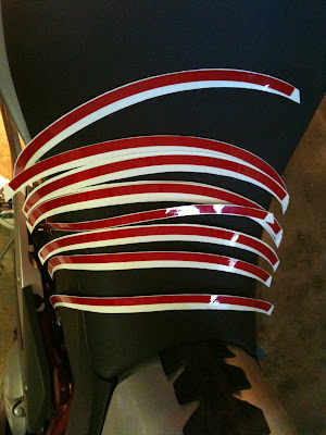
The wheel stripes come on two sheets as shown below:
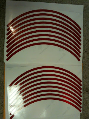
In order to make it easier to handle, I went ahead and cut each strip out separately so I could peel off the backing as I applied the stripe rather than having to peel it all off at once.
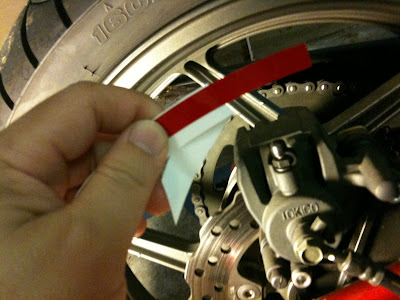
In order to get the stripe lined up as close as possible, I positioned my desk lamp so that the bulb was near the hub of the wheel, shining up towards the rim. By having the same lighting as I moved the bike to rotate the wheel, I figured I'd get the most consistent reflection off the wheel. There appeared to be a bit of a corner edge as the flat face ended moving towards the hub. I chose this transition point to use for lining up the "inside" edge of the wheel stripe. Exposing about an inch and a half to two inches of the stripe, I folded back the backing and lined up the stripe and the edge, then lightly tapped the stripe to make it adhere to the wheel. From there, I'd expose another two inches or so and repeat the process, making sure the "inside" edge lined up with the wheel's edge.
After getting the first stripe on, it was a matter of repeating the process. The instructions said to butt the edges of the stripes together, but the stripes are considerably longer the 1/4 of the rim circumference, so I went ahead and overlapped the edges by about 1/4", making sure to get the tape down securely at the edge of the preceding stripe. Overall, I think the effect is quite nice. I only had to pull up a couple of sections, but I do not think that compromised the stripes' reflective qualities.
The only issue that I had with the wheel stripes is that sometimes the waxy part of the backing would separate and come up with the wheel stripe. I think this may be because the blade went a hair too far when cutting the reflective stripe material. Usually, I could cut off about 1/4" of the stripe and then slightly fold the corner of the stripe to get it to separate. If the stripe was completely folded, I would simply cut off a little more. As I mentioned before, there was plenty of length to the stripe to do this. I would estimate that by the time I had three of the stripes applied, I would only need 2/3 to 3/4 of the last stripe to complete the wheel.
Another recommendation is to work the part of the wheel that is most accessible towards the top, and then move the bike so that the next piece is being applied to the same location. I tried to go around the wheel without moving the bike at first, and that resulted in having to pull up part of the stripe to reapply it because I simply didn't have a good enough visual angle to get the tape lined up with the edge of the rim. Additionally, it changed the lighting aspect of the wheel, so the placement may be somewhat off compared to the rest of the wheel. Granted, we're talking about maybe a millimeter or two, but it's enough to annoy me since I know where it is.
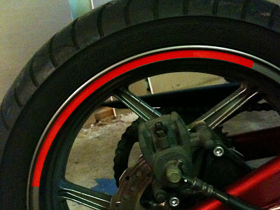
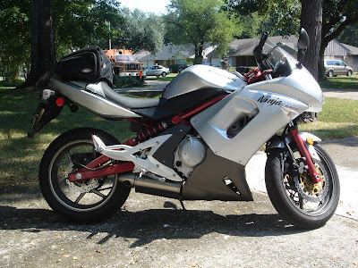
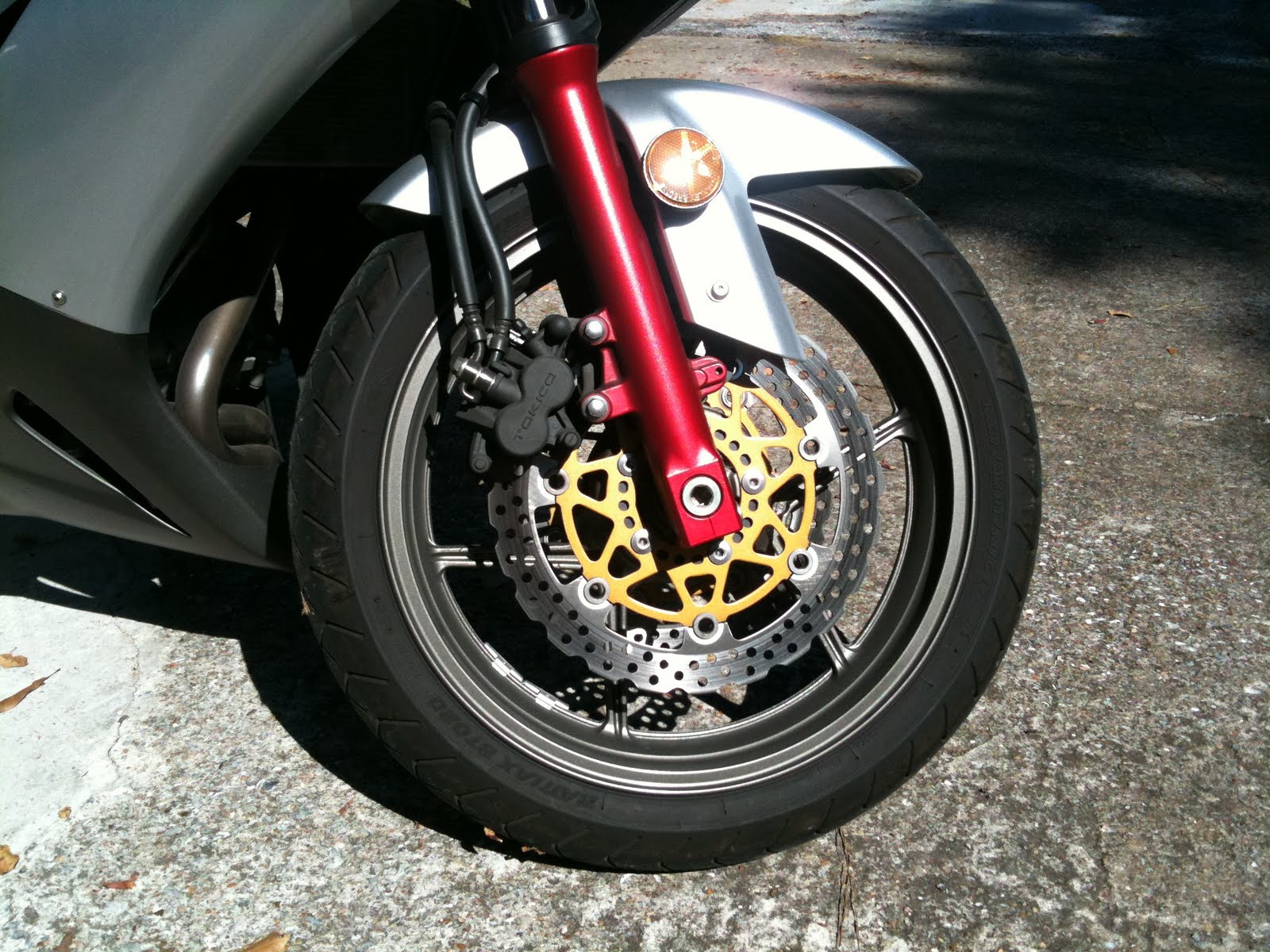
Aside from the reflective properties of the stripes, I think that the dark red rims really add a lot to the visual aesthetics of the bike. The wheels really "pop" now, whereas the were just kind of "there" before. Here are some before and after pictures.
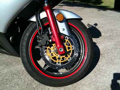
Front wheel before:

Front wheel after:
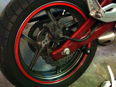
Right side before:
Right side after:

I ordered the reflective stripes because I primarily wanted to increase my visibility from the side for riding at dusk/night. I went with the dark red so that it would match up closely with the frame of the 650R when not reflecting, and I opted to go for the 10mm width, because I wanted to get as much surface area as possible. I can highly recommend the 10mm width as it seems to completely fill up the edge of the wheel quite nicely.
Tools Used:
- Scissors
- Desk lamp
- Paper towels
- All-purpose Glass Cleaner
The installation instructions that came with the stripes were very good, and after reading through them, I felt fully prepared to make a go at this. Before attempting to apply the stripes, I cleaned the surface of the wheels using the paper towels and all-purpose glass cleaner. This was very effective at removing all the road grime and grease that probably came off of the chain on the left side of the rear wheel.
The wheel stripes come on two sheets as shown below:

In order to make it easier to handle, I went ahead and cut each strip out separately so I could peel off the backing as I applied the stripe rather than having to peel it all off at once.

In order to get the stripe lined up as close as possible, I positioned my desk lamp so that the bulb was near the hub of the wheel, shining up towards the rim. By having the same lighting as I moved the bike to rotate the wheel, I figured I'd get the most consistent reflection off the wheel. There appeared to be a bit of a corner edge as the flat face ended moving towards the hub. I chose this transition point to use for lining up the "inside" edge of the wheel stripe. Exposing about an inch and a half to two inches of the stripe, I folded back the backing and lined up the stripe and the edge, then lightly tapped the stripe to make it adhere to the wheel. From there, I'd expose another two inches or so and repeat the process, making sure the "inside" edge lined up with the wheel's edge.

After getting the first stripe on, it was a matter of repeating the process. The instructions said to butt the edges of the stripes together, but the stripes are considerably longer the 1/4 of the rim circumference, so I went ahead and overlapped the edges by about 1/4", making sure to get the tape down securely at the edge of the preceding stripe. Overall, I think the effect is quite nice. I only had to pull up a couple of sections, but I do not think that compromised the stripes' reflective qualities.


The only issue that I had with the wheel stripes is that sometimes the waxy part of the backing would separate and come up with the wheel stripe. I think this may be because the blade went a hair too far when cutting the reflective stripe material. Usually, I could cut off about 1/4" of the stripe and then slightly fold the corner of the stripe to get it to separate. If the stripe was completely folded, I would simply cut off a little more. As I mentioned before, there was plenty of length to the stripe to do this. I would estimate that by the time I had three of the stripes applied, I would only need 2/3 to 3/4 of the last stripe to complete the wheel.
Another recommendation is to work the part of the wheel that is most accessible towards the top, and then move the bike so that the next piece is being applied to the same location. I tried to go around the wheel without moving the bike at first, and that resulted in having to pull up part of the stripe to reapply it because I simply didn't have a good enough visual angle to get the tape lined up with the edge of the rim. Additionally, it changed the lighting aspect of the wheel, so the placement may be somewhat off compared to the rest of the wheel. Granted, we're talking about maybe a millimeter or two, but it's enough to annoy me since I know where it is.
Aside from the reflective properties of the stripes, I think that the dark red rims really add a lot to the visual aesthetics of the bike. The wheels really "pop" now, whereas the were just kind of "there" before. Here are some before and after pictures.
Front wheel before:
Front wheel after:

Right side before:

Right side after:

Friday, August 27, 2010
Fairing Removal
In my wanderings via Google, I did find a good video on YouTube about how to remove the Ninja 650R's fairings. The only problem that I have with it is that it isn't quite accurate, because the poster left out a critical step to remove two hidden screws that attach the upper fairings to the instrument cowl. He apparently had removed them previously in order to be able to remove the upper fairings without having to get behind the instrument cowl.
If you read my post re: installing the R&G Racing Frame Sliders, then you know that I advocate the complete removal of the 650R's bodywork in order to fully expose the frame. The process is the same for both sides. So here's how it's done.
(One more thing to note. These instructions are for removing the fairing for the purpose of installing the sliders. It does not include removal of the front cowl and headlight assembly. However once you do all this, I can't imagine that it's too tough to figure out the rest.)
Tools Used:
- Ratchet
- 3/8" driver ratchet extension
- 4mm hex key driver
- No. 2 phillips head screwdriver
- Flat head screwdriver
Using the ratchet with the extension and 4mm hex key driver, remove the four 4mm hex socket screws holding the windscreen in place (two per side). Place these screws by themselves so they don't get mixed up with other similar screws.
NOTE: All of these screws have transparent plastic washers. Be careful that you do not lose them or drop them as you remove the screws. I use a magnetic tray to hold all of the fasteners. Unfortunately, not all of the fasteners are magnetic, but it's better than nothing.
The windscreen with the screws removed: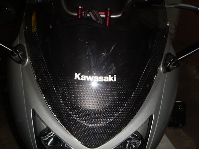
Gently pull the top of the windscreen towards the front of the bike to lift it off. There is a tape-like gasket on either side of the windscreen. Be careful not to remove it. On my bike, one side stayed on the cowl, the other stayed on the windscreen. There is a tab at the front of the windscreen to attach it to the cowl. Pull the windscreen out of the slot and store it somewhere safe.
Windscreen tab: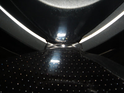
Next, you need to remove the side cockpit trim panels on either side of the instrument pod. There should be two 4mm hex socket screws each. Remove them, and the trim panel should easily slide back and out. Place these screws together so they don't get mixed up with the windscreen screws.
NOTE: I forgot to take a picture at this step. Ninja 650R owners should know what I'm talking about, but I'll get a pick and insert it here tomorrow if I get a chance.
On both sides of the instrument pod, you should now see a phillips head screw. Remove these screws with a No. 2 phillips head screwdriver. These hold both the upper fairing as well as the instrument pod cowl. You should now be able to remove the instrument pod cowl.
REINSTALLATION NOTE: When reinstalling the instrument pod cowl, be sure that it is seated firmly on the plastic silver side pieces and not on the windscreen's gasket if the gasket decided to stick with the bike.
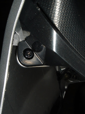
Removing the instrument pod cowl will reveal another screw that is holding the upper fairing on. This is the screw that was omitted from the YouTube video I saw. There is also another screw on the bottom of the nose beneath the headlight. Remove these two screws with a No. 2 phillips head screwdriver.
Second screw hidden by instrument pod cowl (top):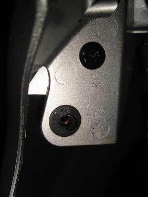
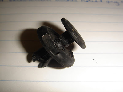
Now that the top of the bike is exposed, let's go down to the bottom and work our way back up. The lower fairing halves are connected at the bottom by what I call push-plug fasteners. They are basically plastic grommets that get pushed into a hole, and then a central plunger is pushed in, which splays the "legs" of the grommet, preventing it from coming out. There are three of these to remove: one on the front of the lower fairing and two on the bottom.
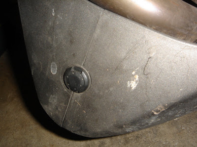
Take a flathead screwdriver, place the tip in the notch of the ring, and pry up the edge of the central plunger. Eventually, the plunger will pull up all the way, and you can then pull it out the rest of the way. Here is what it looks like after it has been removed.
REINSTALLATION NOTE: To reinstall, simply line up the lower fairings, push the plug into the hole, and then push down the central plunger.
The lower fairing is also connected by three 4mm hex socket screws. (See picture below.) The screw towards the rear (left in the picture) has a grommet, and it can only be mounted here. The other two screws (four total) need to be put somewhere separate from the windscreen and cockpit trim panel screws, because they are longer. Even if screws are the same, I like to try to put the screws back where they came from. In fact, I had one screw that would not go in even though it was the same as its partner, but when I tried its partner, it went right in without any problem.
Lower fairing showing three screws: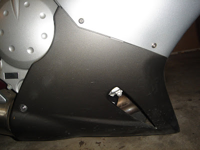
Even without the screws now, there are two plastic clips holding the lower and upper fairings together. The picture below shows one, but there's another one towards the front that I didn't discover until I was reinstalling the bodywork. To remove the lower fairing, gently pull the bottom of the fairing out and slight up. You will hear a loud snap, which should be the clips unsnapping. Hopefully you didn't actually break anything. Set the lower fairings aside and out of the way.
Inside clip connecting lower and upper fairings: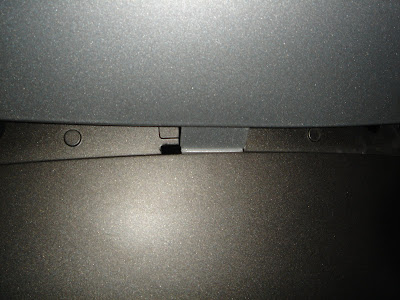
This should leave one 4mm hex socket screw holding the upper fairing to the bike. Again, this screw has a grommet and can only be installed at this location.
NOTE 1: The picture below shows the cockpit trim panel still in place. This is because I took the picture when I was working on the right side and did not fully remove the bodywork. Following these directions, the panel at the top of the picture and the screw holding it on will have already been removed.
NOTE 2: These four screws (two per side) will actually stick to the magnetic tray.
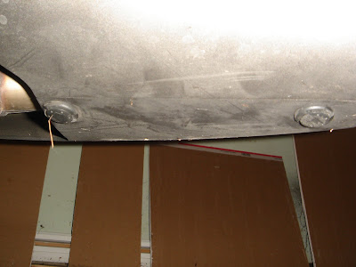
Upper fairing fasteners: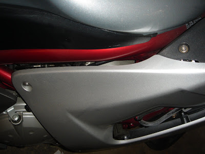
At this point, the upper fairing is pretty much being held on by a slot connector up front and a snap-in mounting point down low. The picture below shows the snap-in mount on the left side:
Upper fairing mount: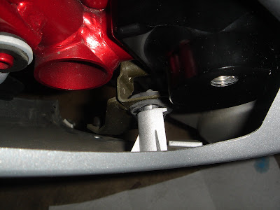
A gentle tug will pull the upper fairing free of the snap-in mount, and you should be able to simply slide the upper fairing towards the front of the bike to free it from the bike.
CAUTION: There is a wire connecting the turn signal to the electrical system. Be sure to disconnect the turn signal and pull the connecting wire free of the retention rings on the inside of the upper fairing.
Inside of upper fairing (note the wire and retention ring:
Upper fairing mounting slot in cowl: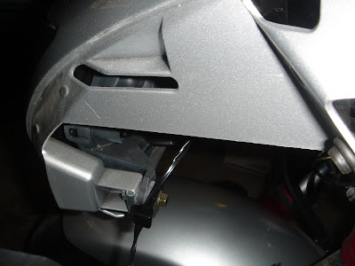
Turn signal plug: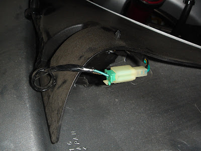
You should now have full access to the frame on both sides.
To reinstall the bodywork, simply reverse the steps. I've made a few reinstallation notes along the way.
ALTERNATE PROCESS: Remove the lower fairings first, and then start at the top.
DISCLAIMER: This blog is purely for information sharing purposes. Anything you do to your bike is at your sole discretion, and I cannot be held responsible for any badness that may occur while attempting any of these activities.
If you read my post re: installing the R&G Racing Frame Sliders, then you know that I advocate the complete removal of the 650R's bodywork in order to fully expose the frame. The process is the same for both sides. So here's how it's done.
(One more thing to note. These instructions are for removing the fairing for the purpose of installing the sliders. It does not include removal of the front cowl and headlight assembly. However once you do all this, I can't imagine that it's too tough to figure out the rest.)
Tools Used:
- Ratchet
- 3/8" driver ratchet extension
- 4mm hex key driver
- No. 2 phillips head screwdriver
- Flat head screwdriver
Using the ratchet with the extension and 4mm hex key driver, remove the four 4mm hex socket screws holding the windscreen in place (two per side). Place these screws by themselves so they don't get mixed up with other similar screws.
NOTE: All of these screws have transparent plastic washers. Be careful that you do not lose them or drop them as you remove the screws. I use a magnetic tray to hold all of the fasteners. Unfortunately, not all of the fasteners are magnetic, but it's better than nothing.
The windscreen with the screws removed:

Gently pull the top of the windscreen towards the front of the bike to lift it off. There is a tape-like gasket on either side of the windscreen. Be careful not to remove it. On my bike, one side stayed on the cowl, the other stayed on the windscreen. There is a tab at the front of the windscreen to attach it to the cowl. Pull the windscreen out of the slot and store it somewhere safe.
Windscreen tab:

Next, you need to remove the side cockpit trim panels on either side of the instrument pod. There should be two 4mm hex socket screws each. Remove them, and the trim panel should easily slide back and out. Place these screws together so they don't get mixed up with the windscreen screws.
NOTE: I forgot to take a picture at this step. Ninja 650R owners should know what I'm talking about, but I'll get a pick and insert it here tomorrow if I get a chance.
On both sides of the instrument pod, you should now see a phillips head screw. Remove these screws with a No. 2 phillips head screwdriver. These hold both the upper fairing as well as the instrument pod cowl. You should now be able to remove the instrument pod cowl.
REINSTALLATION NOTE: When reinstalling the instrument pod cowl, be sure that it is seated firmly on the plastic silver side pieces and not on the windscreen's gasket if the gasket decided to stick with the bike.

Removing the instrument pod cowl will reveal another screw that is holding the upper fairing on. This is the screw that was omitted from the YouTube video I saw. There is also another screw on the bottom of the nose beneath the headlight. Remove these two screws with a No. 2 phillips head screwdriver.
Second screw hidden by instrument pod cowl (top):

Now that the top of the bike is exposed, let's go down to the bottom and work our way back up. The lower fairing halves are connected at the bottom by what I call push-plug fasteners. They are basically plastic grommets that get pushed into a hole, and then a central plunger is pushed in, which splays the "legs" of the grommet, preventing it from coming out. There are three of these to remove: one on the front of the lower fairing and two on the bottom.


Take a flathead screwdriver, place the tip in the notch of the ring, and pry up the edge of the central plunger. Eventually, the plunger will pull up all the way, and you can then pull it out the rest of the way. Here is what it looks like after it has been removed.
REINSTALLATION NOTE: To reinstall, simply line up the lower fairings, push the plug into the hole, and then push down the central plunger.

The lower fairing is also connected by three 4mm hex socket screws. (See picture below.) The screw towards the rear (left in the picture) has a grommet, and it can only be mounted here. The other two screws (four total) need to be put somewhere separate from the windscreen and cockpit trim panel screws, because they are longer. Even if screws are the same, I like to try to put the screws back where they came from. In fact, I had one screw that would not go in even though it was the same as its partner, but when I tried its partner, it went right in without any problem.
Lower fairing showing three screws:

Even without the screws now, there are two plastic clips holding the lower and upper fairings together. The picture below shows one, but there's another one towards the front that I didn't discover until I was reinstalling the bodywork. To remove the lower fairing, gently pull the bottom of the fairing out and slight up. You will hear a loud snap, which should be the clips unsnapping. Hopefully you didn't actually break anything. Set the lower fairings aside and out of the way.
Inside clip connecting lower and upper fairings:

This should leave one 4mm hex socket screw holding the upper fairing to the bike. Again, this screw has a grommet and can only be installed at this location.
NOTE 1: The picture below shows the cockpit trim panel still in place. This is because I took the picture when I was working on the right side and did not fully remove the bodywork. Following these directions, the panel at the top of the picture and the screw holding it on will have already been removed.
NOTE 2: These four screws (two per side) will actually stick to the magnetic tray.
Upper fairing fasteners:

At this point, the upper fairing is pretty much being held on by a slot connector up front and a snap-in mounting point down low. The picture below shows the snap-in mount on the left side:
Upper fairing mount:

A gentle tug will pull the upper fairing free of the snap-in mount, and you should be able to simply slide the upper fairing towards the front of the bike to free it from the bike.
CAUTION: There is a wire connecting the turn signal to the electrical system. Be sure to disconnect the turn signal and pull the connecting wire free of the retention rings on the inside of the upper fairing.
Inside of upper fairing (note the wire and retention ring:

Upper fairing mounting slot in cowl:

Turn signal plug:

You should now have full access to the frame on both sides.
To reinstall the bodywork, simply reverse the steps. I've made a few reinstallation notes along the way.
ALTERNATE PROCESS: Remove the lower fairings first, and then start at the top.
DISCLAIMER: This blog is purely for information sharing purposes. Anything you do to your bike is at your sole discretion, and I cannot be held responsible for any badness that may occur while attempting any of these activities.
R&G Racing Frame Sliders Installation
As I mentioned before, I looked at some postings on the Internet before diving in, and I found one common thing to NOT be the case. Almost every install thread I read mentioned what a pain it was to remove all the fairings, and that it was quicker to just release the bottom of the upper fairings and install the slider mounting blocks with them pulled out. I tried this method on the right side of my bike, and to be perfectly honest, I found it a serious pain to work with the fairing in the way. For the left side, I decided to remove the upper fairing, and while it took a little more time, it made installing the left slider mounting block a lot easier.
RECOMMENDATION: Remove all the fairings to fully expose the areas of the motorcycle in which you will be working. Any job worth doing well is worth doing right.
The nice thing about the R&G sliders is that they do not require any modifications to the fairings themselves. The way the mounting blocks are designed, the plastic bobbin pokes through the bottom of the vent in the upper fairing. In these two pictures, you can see the frame where the mounting blocks will attach. The bobbin is the sacrificial part in the event of a crash that will hopefully take all the damage instead of the precious bodywork or controls.
Right Side: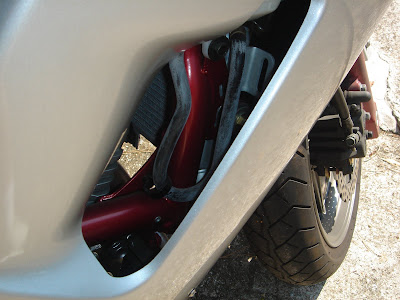
Left Side: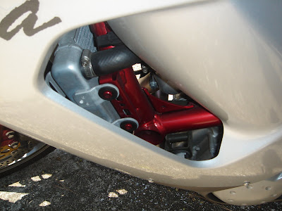
The Installation
Tools Used:
- Ratchet
- 3/8" ratchet driver extension
- 4mm hex key driver (for the bodywork fasteners)
- 5mm hex key driver (for the rear mounting block clamp bolts)
- 6mm hex key driver (for the replacement engine mounting bolt)
- 10mm socket driver (for the existing engine mounting bolt)
- 17mm socket driver (for the bobbin mounting bolt)
- Torque Wrench
- 44 N-m for the engine mounting bolts (see comments re: torque specs)
- 40 N-m (max) for the remaining R&G bolts
- Loctite 242 Blue threadlocker
Despite the fact that I did the right side without removing the fairings, I am going to write this up as if the fairings have been completely removed. I will follow this up with a write up on completely removing the '06-'08 Ninja 650R fairings. It may not be until tomorrow, because I think I may need to take a couple of extra pictures for clarity sake.
So, now that you have all the fairings removed and safely stashed somewhere away from the work area, we will start with the right side slider installation. One of the things that I wondered when I opened the package was "Which mounting block goes on which side?" Once you have the frame exposed, it's actually quite obvious. The easiest way to tell is to look at the bolt holes. The large hole is the engine mounting bolt hole, and it is on the bottom of the mounting block. The two smaller clamp bolt holes go toward the rear of the bike. So for the right-side mounting block, the two smaller clamp bolt holes are on the left, and the engine mounting bolt hole is on the right. Vice-versa for the left-side mounting block. In the end, they can only be mounted on their intended sides, which is obvious now, but not before you remove the bodywork.
For Right Side: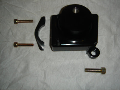
For Left Side: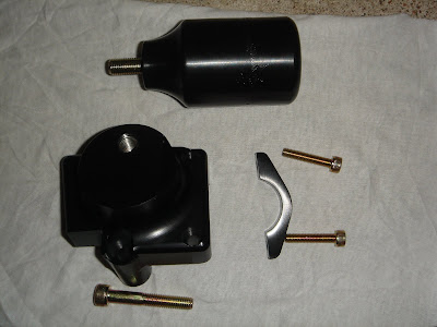
Aside from the fact that the mounting blocks look different, the installation procedure is the same.
Using the ratchet with a 10mm socket driver, remove the engine mounting bolt that lines up with the large hole on the mounting block. This is the silver bolt on the underside of the red painted frame. Set this bolt aside. You will not be using it again. (You should have two at the end of this exercise.)
Right Side: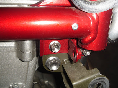
Left Side: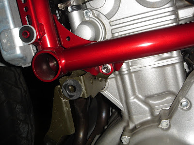
If you're not sure, you can always hold the mounting block up to the frame to see which of the bolts lines up.
Right Side: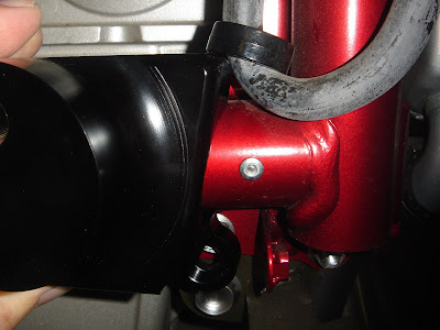
Left Side: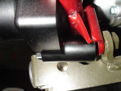
There are two M8 hex socket bolts provided in the R&G package. The shorter one goes on the right, longer one goes on the left side. If you put each on in their respective mounting block, you'll see that the amount of revealed thread is the same. If not, you have them in the wrong block. You can see in the pictures above that the left mounting block requires a longer engine mounting bolt. You need to use a 6mm hex key driver for these bolts.
Push the M8 engine mounting bolt through the bottom hole in the mounting block and apply one drop of Loctite 242 Blue threadlocker to the threads. (See Woodcraft Swingarm Spools Installation for more on threadlocker.) Tighten the bolt just to the point that it is snug, but do not tighten any further yet. I had to use the ratchet extension with the 6mm hex key driver to get this done. If you have T-handle hex drivers, that works, too. This will hold the mounting block in place while you fasten the rear mounting bolts to the clamp.
Apply a drop of threadlocker to one of the M6x30mm clamp bolts and push it through the top hole at the rear of the mounting block. Take the black curved clamp and place it on the inside face of the frame opposite the two bolt holes of the mounting block and screw the top clamp bolt in just far enough for it to hold. Apply a drop to a second M6x30mm clamp bolt, push it through the bottom hole, and tighten it. Using a 5mm hex key driver, tighten one bolt until it is snug, then tighten the other bolt until it is equally snug.
Take the torque wrench with the 6mm hex key driver, set it to 44 N-m, and tighten the engine mounting bolt. (See Woodcraft Swingarm Spools Installation for more on using the torque wrench.)
Now switch the 6mm to the 5mm driver, set the torque wrench to 40 N-m, and tighten the clamp bolts on the rear of the mounting block. I made sure to tighten them at the same rate, e.g. 1/4 turn on the top, 1/4 on the bottom, repeat. Keep in mind that the 40 N-m is a maximum value. I found that two of the four M6x30 sockets started to strip before the torque wrench clutch gave way, so you may not necessarily reach the max bolt torque. Unfortunately, I do not know at what torque value this happened, but I am confident that it is sufficient to keep the mounting block in place in conjunction with the properly torqued engine mounting bolt. Congratulations, you now have two properly mounted slider mounting blocks.
NOTE: This part of the installation is where it's a serious pain to have the fairing still attached, because you're constantly trying to push it out of the way, get under it, insert the bolts without a clear view, or try to fit your tools under it. Take the time to remove the fairings, and this will go a lot faster.
Right Side: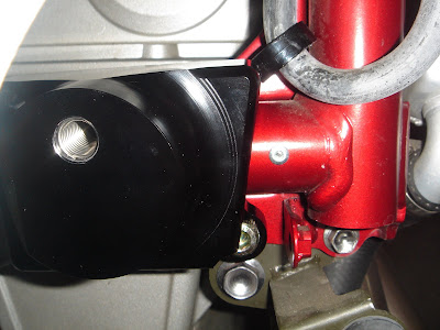
Left Side: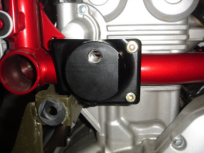
Left Side Rear Clamp: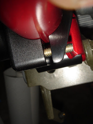
Now that the mounting blocks are in place, it is time to reinstall all of the bodywork. Again, this will be covered in another post. Once the bodywork is back in place, all that remains is to install the bobbins. Take the M10x70mm bolt, slide one M10 washer up to the head, push the bolt through the open end of the bobbin. Now take a 17mm socket, put it on the 3/8" driver ratchet extension, and push the socket into the bobbin until it connects with the bolt head. Keeping the bolt pushed all the way into the bobbin with the ratchet extension, apply one drop of threadlocker to the bolt threads, and carefully start threading the bolt into the slider mounting block. Keep going until it is snug. Take the torque wrench, which should still be set to 40 N-m (if not, set it to 40 N-m), attach the extension with 17mm socket, and carefully tighten the bolt until it slips.
If you grasp the bobbin, you should be able give it a pretty good (and careful) tug or push and feel the bike move as if you were holding the handlebar and doing it. There should not be any play in the mounting block whatsoever.
Congratulations, your new R&G Racing Frame Sliders are now installed!
Right Side: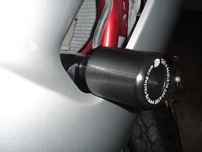
Left Side: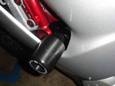
DISCLAIMER: This blog is purely for information sharing purposes. Anything you do to your bike is at your sole discretion, and I cannot be held responsible for any badness that may occur while attempting any of these activities.
RECOMMENDATION: Remove all the fairings to fully expose the areas of the motorcycle in which you will be working. Any job worth doing well is worth doing right.
The nice thing about the R&G sliders is that they do not require any modifications to the fairings themselves. The way the mounting blocks are designed, the plastic bobbin pokes through the bottom of the vent in the upper fairing. In these two pictures, you can see the frame where the mounting blocks will attach. The bobbin is the sacrificial part in the event of a crash that will hopefully take all the damage instead of the precious bodywork or controls.
Right Side:

Left Side:

The Installation
Tools Used:
- Ratchet
- 3/8" ratchet driver extension
- 4mm hex key driver (for the bodywork fasteners)
- 5mm hex key driver (for the rear mounting block clamp bolts)
- 6mm hex key driver (for the replacement engine mounting bolt)
- 10mm socket driver (for the existing engine mounting bolt)
- 17mm socket driver (for the bobbin mounting bolt)
- Torque Wrench
- 44 N-m for the engine mounting bolts (see comments re: torque specs)
- 40 N-m (max) for the remaining R&G bolts
- Loctite 242 Blue threadlocker
Despite the fact that I did the right side without removing the fairings, I am going to write this up as if the fairings have been completely removed. I will follow this up with a write up on completely removing the '06-'08 Ninja 650R fairings. It may not be until tomorrow, because I think I may need to take a couple of extra pictures for clarity sake.
So, now that you have all the fairings removed and safely stashed somewhere away from the work area, we will start with the right side slider installation. One of the things that I wondered when I opened the package was "Which mounting block goes on which side?" Once you have the frame exposed, it's actually quite obvious. The easiest way to tell is to look at the bolt holes. The large hole is the engine mounting bolt hole, and it is on the bottom of the mounting block. The two smaller clamp bolt holes go toward the rear of the bike. So for the right-side mounting block, the two smaller clamp bolt holes are on the left, and the engine mounting bolt hole is on the right. Vice-versa for the left-side mounting block. In the end, they can only be mounted on their intended sides, which is obvious now, but not before you remove the bodywork.
For Right Side:

For Left Side:

Aside from the fact that the mounting blocks look different, the installation procedure is the same.
Using the ratchet with a 10mm socket driver, remove the engine mounting bolt that lines up with the large hole on the mounting block. This is the silver bolt on the underside of the red painted frame. Set this bolt aside. You will not be using it again. (You should have two at the end of this exercise.)
Right Side:

Left Side:

If you're not sure, you can always hold the mounting block up to the frame to see which of the bolts lines up.
Right Side:

Left Side:

There are two M8 hex socket bolts provided in the R&G package. The shorter one goes on the right, longer one goes on the left side. If you put each on in their respective mounting block, you'll see that the amount of revealed thread is the same. If not, you have them in the wrong block. You can see in the pictures above that the left mounting block requires a longer engine mounting bolt. You need to use a 6mm hex key driver for these bolts.
Push the M8 engine mounting bolt through the bottom hole in the mounting block and apply one drop of Loctite 242 Blue threadlocker to the threads. (See Woodcraft Swingarm Spools Installation for more on threadlocker.) Tighten the bolt just to the point that it is snug, but do not tighten any further yet. I had to use the ratchet extension with the 6mm hex key driver to get this done. If you have T-handle hex drivers, that works, too. This will hold the mounting block in place while you fasten the rear mounting bolts to the clamp.
Apply a drop of threadlocker to one of the M6x30mm clamp bolts and push it through the top hole at the rear of the mounting block. Take the black curved clamp and place it on the inside face of the frame opposite the two bolt holes of the mounting block and screw the top clamp bolt in just far enough for it to hold. Apply a drop to a second M6x30mm clamp bolt, push it through the bottom hole, and tighten it. Using a 5mm hex key driver, tighten one bolt until it is snug, then tighten the other bolt until it is equally snug.
Take the torque wrench with the 6mm hex key driver, set it to 44 N-m, and tighten the engine mounting bolt. (See Woodcraft Swingarm Spools Installation for more on using the torque wrench.)
Now switch the 6mm to the 5mm driver, set the torque wrench to 40 N-m, and tighten the clamp bolts on the rear of the mounting block. I made sure to tighten them at the same rate, e.g. 1/4 turn on the top, 1/4 on the bottom, repeat. Keep in mind that the 40 N-m is a maximum value. I found that two of the four M6x30 sockets started to strip before the torque wrench clutch gave way, so you may not necessarily reach the max bolt torque. Unfortunately, I do not know at what torque value this happened, but I am confident that it is sufficient to keep the mounting block in place in conjunction with the properly torqued engine mounting bolt. Congratulations, you now have two properly mounted slider mounting blocks.
NOTE: This part of the installation is where it's a serious pain to have the fairing still attached, because you're constantly trying to push it out of the way, get under it, insert the bolts without a clear view, or try to fit your tools under it. Take the time to remove the fairings, and this will go a lot faster.
Right Side:

Left Side:

Left Side Rear Clamp:

Now that the mounting blocks are in place, it is time to reinstall all of the bodywork. Again, this will be covered in another post. Once the bodywork is back in place, all that remains is to install the bobbins. Take the M10x70mm bolt, slide one M10 washer up to the head, push the bolt through the open end of the bobbin. Now take a 17mm socket, put it on the 3/8" driver ratchet extension, and push the socket into the bobbin until it connects with the bolt head. Keeping the bolt pushed all the way into the bobbin with the ratchet extension, apply one drop of threadlocker to the bolt threads, and carefully start threading the bolt into the slider mounting block. Keep going until it is snug. Take the torque wrench, which should still be set to 40 N-m (if not, set it to 40 N-m), attach the extension with 17mm socket, and carefully tighten the bolt until it slips.
If you grasp the bobbin, you should be able give it a pretty good (and careful) tug or push and feel the bike move as if you were holding the handlebar and doing it. There should not be any play in the mounting block whatsoever.
Congratulations, your new R&G Racing Frame Sliders are now installed!
Right Side:

Left Side:

DISCLAIMER: This blog is purely for information sharing purposes. Anything you do to your bike is at your sole discretion, and I cannot be held responsible for any badness that may occur while attempting any of these activities.
Woodcraft Swingarm Spools Installation
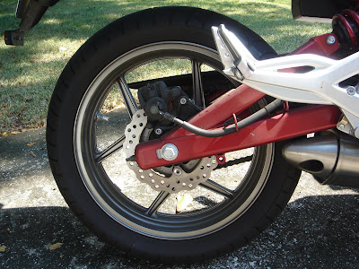
Since this was my first attempt at doing anything to the 650R, I decided to start with the easier of the two installations - the Woodcraft swingarm spools. These go on the bottom of the swingarm on each side where there are threaded holes specifically for this application. If you look at the picture below, you can see the mounting hole just to the right of the brake rotor.
Tools Used:
- Ratchet
- 8mm hex key driver
- Torque Wrench set to 10 ft-lbs
- Loctite 242 Blue threadlocker
- 409 cleaner
- Q-tips
The first thing I did was clean the threads on the swingarm, since they've been exposed to the elements as I've been riding around. I just used some 409 and Q-tips and swabbed out the threads. Then I took a dry Q-tip to remove any excess 409 that remained in the threads.
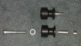
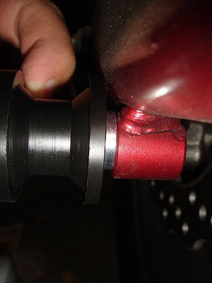
The kit comes with the spools, aluminum sleeve, mounting bolt with hex socket head, washer and aluminum spacer. An email consult with Gary revealed that the aluminum spacer is only necessary if the spool does not clear the swingarm. Here's a picture of the correct order of assembly.
As you can see here in this test fit, the spool just barely clears the edge of the swingarm. It may not be obvious, but the spool actually is not touching the swingarm.
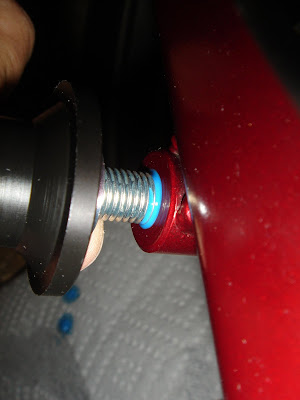
After screwing in the mounting bolt just a few threads in by hand, I applied a drop of the Loctite 242 Blue to the threads. I am a proponent of always using threadlocker in metal-to-metal connections that are subject to vibrations, and I think this situation meets that criteria. A little dab will do you for sure. Do NOT touch the tip of the Loctite bottle to the metal as that will cause chemical reactions that will ruin the remainder of the bottle. I put some paper towels on the floor beneath the bolts to catch any errant fluid.
As you screw in the bolt, the threadlocker naturally distributes itself along the threads as the bolt winds its way into the swingarm. When I couldn't make any progress using my fingers, I used the ratchet with an 8mm hex key driver to get it snug. Then I switched to the torque wrench, which was set at 10 ft-lbs per Gary's recommendation, and finished it up. When using a torque wrench, use a slow and steady amount of pressure on the handle only. When you feel the first "click" give way, then you are done. Do not keep going or you may over torque the bolt even though the clutch is still "clicking".
And here is the finished product, attached and torqued properly.
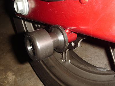
The left side is exactly the same as the right, including not needing the optional spacer.
DISCLAIMER: This blog is purely for information sharing purposes. Anything you do to your bike is at your sole discretion, and I cannot be held responsible for any badness that may occur while attempting any of these activities.

Tools Used:
- Ratchet
- 8mm hex key driver
- Torque Wrench set to 10 ft-lbs
- Loctite 242 Blue threadlocker
- 409 cleaner
- Q-tips
The first thing I did was clean the threads on the swingarm, since they've been exposed to the elements as I've been riding around. I just used some 409 and Q-tips and swabbed out the threads. Then I took a dry Q-tip to remove any excess 409 that remained in the threads.
The kit comes with the spools, aluminum sleeve, mounting bolt with hex socket head, washer and aluminum spacer. An email consult with Gary revealed that the aluminum spacer is only necessary if the spool does not clear the swingarm. Here's a picture of the correct order of assembly.

As you can see here in this test fit, the spool just barely clears the edge of the swingarm. It may not be obvious, but the spool actually is not touching the swingarm.

After screwing in the mounting bolt just a few threads in by hand, I applied a drop of the Loctite 242 Blue to the threads. I am a proponent of always using threadlocker in metal-to-metal connections that are subject to vibrations, and I think this situation meets that criteria. A little dab will do you for sure. Do NOT touch the tip of the Loctite bottle to the metal as that will cause chemical reactions that will ruin the remainder of the bottle. I put some paper towels on the floor beneath the bolts to catch any errant fluid.
As you screw in the bolt, the threadlocker naturally distributes itself along the threads as the bolt winds its way into the swingarm. When I couldn't make any progress using my fingers, I used the ratchet with an 8mm hex key driver to get it snug. Then I switched to the torque wrench, which was set at 10 ft-lbs per Gary's recommendation, and finished it up. When using a torque wrench, use a slow and steady amount of pressure on the handle only. When you feel the first "click" give way, then you are done. Do not keep going or you may over torque the bolt even though the clutch is still "clicking".

And here is the finished product, attached and torqued properly.

The left side is exactly the same as the right, including not needing the optional spacer.
DISCLAIMER: This blog is purely for information sharing purposes. Anything you do to your bike is at your sole discretion, and I cannot be held responsible for any badness that may occur while attempting any of these activities.
Why We're Here
Okay, so in November 2006, I bought my first motorcycle, bringing to fruition a plan that was set in motion as far back as May 1994 when I took the Motorcycle Safety Course. I fully intended to install frame sliders to protect the fairings, but I just never really got to it for one reason or another, not the least of which was procrastination. So earlier this month, a friend of mine bought his first bike and got me motivated to finally getting around to installing these protective/safety items.
So I placed an order with Gary Schilling at www.blueridgeperformance.net for some R&G Racing Frame Sliders and Woodcraft swingarm spools. The reason I went with the R&Gs is because they don't require you to drill into the fairings, which is a big plus to me. They also seem to be the sliders of choice for Ninja 650R owners.
I also placed an order with Graphic Language (http://www.glsigns.com/) for some reflective rim tape. The tape is a dark red, which should match the frame on my 650R, and it's reflective which will increase my conspicuity at night. Never hurts to be easily seen.
When I received the package from Gary, I found R&G's included instructions somewhat lacking. It was basically a page of text without any pictures. Judge for yourself: R&G Instructions. Being rather OCD about things like this, I like to be able to go through the installation process before actually touching the bike, so I did a search on the Internet. I found partial fairing removal instructions and partial slider installation instructions, but nothing that took me from start to finish. Granted, once you get into it, the slider installation is fairly obvious, but it would be nice to be able to see things and how they go together ahead of time.
So I decided to take pictures as I went so that people could learn from my experience. I will also post them separately so that people can look at whichever installation they like without having to scroll through everything.
DISCLAIMER: This blog is purely for information sharing purposes. Anything you do to your bike is at your sole discretion, and I cannot be held responsible for any badness that may occur while attempting any of these activities.
Subscribe to:
Posts (Atom)